 Crystallographic Topology 101

Crystallographic Morse Function
Our model for the crystallographic Morse function is based on concepts familiar to crystallographers who must deal with crystallographic three-dimensional density functions on a frequent basis. The crystallographic observations are in the domain of Bragg reflection intensities which, after solving the phase problem, become Fourier coefficients in a three dimensional summation that gives the density at any chosen point. The density may be electron density or nucleus thermal motion density depending on the type of Bragg diffraction intensities, x-ray or neutron.
A 3-dimensional grid of density values can be calculated on which an interpolated equidensity contour map is drawn. This is then interpreted in terms of atom positions that are smeared out by a combination of thermal motion (Johnson and Levy, 1974) and electron orbital quantum chemistry effects (Coppens, 1996). Once the atoms are found, a reverse Fourier transform calculation is carried out based on the atom positions and the functions that describe the smearing factors to get calculated Fourier amplitudes, which can then be compared with the observations. The various parameters for position and smearing are adjusted in a least-squares calculation.
The thermal motion smearing factor most often used is the 3-dimensional normal probability density function, which is also called the Gaussian density function. The density function for an individual atom may be either isotropic with spherical equidensity contours or anisotropic with ellipsoidal equidensity contours, depending on the site symmetry for the atom within the crystal With neutron diffraction, there is no extra smearing due to the electron orbitals within an atom since neutrons are primarily scattered by the point-like nucleus of an atom and not by the electrons. For x-rays the situation is reversed and an atomic form factor is required in addition to the thermal motion density function. Since our crystallographic experimental interests center around neutron diffraction, we have less interest in electron cloud effects than those scientists who specialize in x-ray diffraction.
The Gaussian density function has tails that extend to infinity; hence with positive scatterers, the summed density function within the crystal never goes to zero. Thus, the tails of the thermal motion density functions for all the atoms in the entire crystal overlap, but the density between atoms is considerably less than the density at the atomic sites. This theoretical global density function is the basic model on which we do critical point analysis. We completely ignore all quantum chemistry electron orbital effects, many of which can in fact be observed in the experimental electron density map of x-ray diffraction when great care is taken in the experimental data collection and correction stages of the analysis. A topological interpretation of the quantum chemistry effects is given in Bader (1991).
Mildly overlapping Gaussian density functions in a space group provide a smooth infinitely differentiable function involving Hermite polynomials and is ideally suited for Morse theory. The atom centroid (mean or first moment of the normal probability density function) is to a first approximation at a mode (extremum) of the density; thus peak positions correspond with atom positions. Our working hypothesis is that all valid real stable crystal structures are Morse functions, which by definition have no degenerate critical points.
Morse Theory
The first application of Morse theory to crystal physics was by van Hove (1953), who showed that certain singularities in lattice dynamics originate from crystallographic symmetry. Morse theory has a nice qualitative treatment in El'sgol'c (1964). The standard mathematical references for Morse theory are Morse (1938) and Milnor (1969); but our application, which involves equivariant topology (Bierstone, 1980), seems to require the treatment by Goresky and MacPherson (1983, 1988). The concepts of peak and pit are purely topological notions while the saddle type critical points involve in a crucial way the differential structure of the functional and the domain. There are some recent ways of dealing with critical points from non-smooth functionals (Fang, 1995), which may be required in more formal analysis than we present here for Morse functions on orbifolds.
Orbifolds are not smooth manifolds except for the few instances involving the 10 (or 13 depending on conventions used) examples of space groups without fixed points. Some formal results concerning Morse functions on orbifolds are also starting to appear in the mathematical preprint literature (e.g., Lerman and Tolman, 1995), but these are primarily based on symplectic rather than Euclidean geometry (cf., Kirwan, 1984), which is beyond our mathematical capabilities to extend into algebraic geometry. In our case we know the Euclidean space analogues of our Morse functions on orbifolds are well behaved so we can always unfold back to Euclidean 3-space for detailed analysis when necessary.
D-Symbol Tiling Alternative
A technique related to our Morse function critical net approach is the Delonay-Dress D-symbols method used by Dress, Huson, and Molnar (1993) and Molnar (1994). That method, which is currently more automated but also more restricted in its crystallographic applicability than ours, uses topological space tiling. The space tiles are based on four types of special positions interpretable as vertices, edges, faces, and centers of polyhedra. The method produces a decomposition of each polyhedron into component simplex tetrahedra. The critical net and the D-symbol approaches lead to identical results in most cases where their method is applicable. Additional details on the D-symbol approach are available on Huson's WWW page.
We found some discrepancies between the Dress, Huson, and Molnar (1993) paper and our results. Their "special rhombohedral" tiling example, which is not a Morse function, is actually body-centered cubic based on vertex positions as illustrated later in Fig. 3.4 and Fig. 4.2. Their "covered rhombohedron" is not a Morse function either since there are not enough pales to fill all the faces. Our working hypothesis is that all real crystal structures are Morse functions (i.e., they have no degenerate critical points). Degenerate critical points suggest structural instability which should be present only during a phase transition.
Chemical Faces and Cages
A detailed list of critical net properties is given at the end of this section. The following chemically-oriented nomenclature allows structural chemistry intuition to be used more easily in interpretation of critical net drawings. First, we note that peaks always represent atoms and passes sometimes, but not always, represent chemical bonds. We define a "chemical face" in a critical net as a disk containing one pale bounded by a graph circuit containing alternating peak and pass nodes with edges along their interconnecting separatrices lines. A "chemical cage" is defined as a configuration of chemical faces that encloses one pit. A chemical cage is a convex polyhedron only in the simplest cases such as primitive cubic, body-centered cubic and face-centered cubic critical nets.
We could have used the term minimal-surface face instead of chemical face, but that would require us to explore yet another major subfield of topology [i.e., minimal surfaces, e.g., Pitts and Rubinstein (1995)]. However, if the reader prefers to interpret the critical net drawings in terms of mathematical minimal surfaces rather than more intuitive chemical surfaces, that interesting option is available.
The universal geometric pattern in critical nets is: (a) the three or more passes attached to a pale will be approximately coplanar with the pale, and the approximately plane-normal critical-net connection at the pale will go to two pits, one on each side; and (b) the three or more pales attached to a pass will be approximately coplanar with the pass, and the approximately plane-normal critical-net connection at the pass will go to two peaks, one on each side. It is advisable to forgo all the distance and angle metric local detail so characteristic of structural crystallography while doing crystallographic topology.
Diamond Critical Net
Fig. 3.1 is a stereoscopic drawing of one chemical cage and the neighboring pits for the diamond structure. It has non-planar chemical faces and thus the diamond chemical cage is not a convex polyhedron. In diamond, there is one unique tetrahedral chemical cage with chair-shaped chemical faces.
[Stereoscopic drawings are best viewed using an inexpensive stereo viewer, such as that available from Edmund Scientific Co., Edscorp Building, Barrington NJ 088007-1380, USA. Fax 609-573-6295). They can also be viewed using "occular gymnastics" (i.e., by holding the figure close to your eyes and then gradually moving the figure to a normal reading distance). High resolution copies of these stereoscopic drawings are available as Postscript or HPGL files by clicking here. The ORTEP input data files in the same directory provide full crystallographic and graphic details on the illustrations.]
Graphite Critical Net
The peak, pass, pale, and pit critical points for the P63/mmc
graphite structure, illustrated below in Fig.
3.2, are at Wyckoff sites b+c, a+h, d+g, and f (with z = -.03),
respectively. Two chemical cages are shown in the graphite illustration
to clarify the packing arrangement, but only one is unique. If one is
conditioned by training to always look for convex polyhedra with atoms
at the vertices, the single unique tetrahedral chemical cage with one
planar and three chair-shaped chemical faces might mistakenly be
interpreted as a hexagonal prism polyhedron with three of the vertex
atoms pinched together at one end of the prism. The disturbing
feature of the prism
interpretation is the existence of a pseudo face of zero area in
the pinched end of the prism. We call this the "graphite paradox". All
the graphite chemical bonding is in the flat six membered chemical face
of the tetrahedron.
Hexagonal Diamond Critical Net
In addition to the cubic diamond and hexagonal graphite structures
shown above, there is a third simple carbon structure called hexagonal
diamond, which has the critical net illustrated in Fig. 3.3. This
structure, which is not widly known since it is hard to find in
natural sources and is difficult to synthesize, crystallizes in the same
space group as graphite. It has both boat- and chair-shaped six-membered
rings and two different chemical cages. The graphite and
hexagonal diamond critical nets may seem quite different, but they
are topologically equivalent through duality as discussed later
in Sect. 5. and
Fig. 5.3.
BCC Critical Net
A common critical net, body-centered cubic (bcc), is shown
in Fig. 3.4 and discussed in detail in Sect. 4.
There is only one type of chemical cage, but again for packing
illustration, two are shown in the figure. Bcc is the ultimate example
of warped chemical faces. There are four puckered chemical faces,
each containing four peaks and four bonds. The pales in the four faces
have a square planar arrangement about the pit, but the 6 peaks are
octahedral about the pit because of the vertex sharing arrangement.
Using the basic bcc elemental structure of space group Im
Y** Lattice Complex Critical Net
The previous critical net drawings (Figs. 3.1-3.5) have four- or
six-atom chemical faces. An example with five-atom chemical faces is the
Y** lattice complex shown in Fig. 3.6. Four pentagonal chemical faces
join to form a tetrahedral chemical cage.
FCC Critical Net
The face-centered cubic critical net, shown in Fig. 3.7, has a
three-fold planar coordinations of peaks (and passes) around pales and,
in addition, has two independent face-sharing
chemical cages as adjoining
tetrahedral and octahedral convex polyhedra.
Only some of the pales are required by symmetry to be exactly in the
plane of the chemical faces.
Critical Net Characteristics
Below are some definitive characteristics that are useful for finding
and analyzing
critical nets for very simple structures. For more complex
structures, critical point positions and the canonical paths joining
them can be determined numerically from calculated
global Gaussian thermal motion density maps based only on given
atomic (i.e., peak) positions.
The author's ORCRIT program for
protein electron density map interpretation, originally written in 1977,
could be modified for that purpose.
High precision experimental
electron density maps from x-ray data and charge density maps
calculated by ab initio quantum chemistry programs are more
complicated than those considered here because of the possible
addition of new
critical points caused by bonding electrons etc.
Local vs. Global Topology
At this point we note a limitation in the critical net illustrations
shown in Figs. 3.1-3.7 in that they provide only local topology
information. There is often inadequate topological information
available in drawings of critical points around pits (i.e.,
chemical cages) to fully characterize the structure. For example, a
hexagonal close-packed (hcp) critical net illustration looks identical
to the fcc illustration in Fig. 3.5 since the numbers of critical
points in the two basic units (defined above) are the same [i.e.,
(1,6,8,3)]. However, the unit cell counts are (4,24,32,12) for fcc and
(2,12,16,6) for hcp, suggesting the presence of a superstructure in fcc.
The two structures have identical local topology since each is made up
of layers of atoms packed hexagonally with layers interleaved to produce
the densest possible packing. However, fcc has an ABCABC... layer
sequence in space group Fm
Page last revised: June 3, 1996
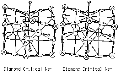
Figure 3.1. Critical Net Illustration of Diamond.
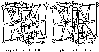
Figure 3.2. Critical Net Illustration of Graphite.
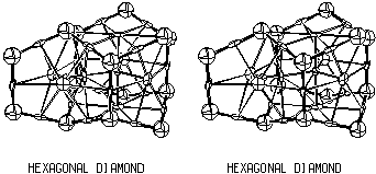
Figure 3.3. Critical Net Illustration of Hexagonal Diamond.
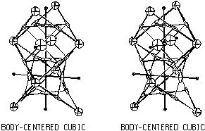
Figure 3.4. Critical Net Illustration of Body-Centered
Cubic.
 m as a template, binary compounds can also be fitted
into the same basic structure. For example, the Fd
 m space group can accommodate two different atoms on the
two
  3m sites as shown it Fig. 3.5. This bcc
derivative is our Morse function alternative to the special
rhombohedron tiling of Dress, Huson and Molnar (1993).
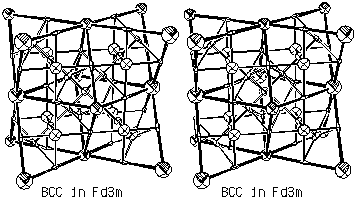
Figure 3.5. Critical Net Illustration of Hypothetical Body-Centered
Cubic Binary Structure.
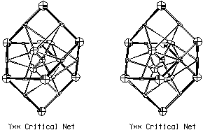
Figure 3.6. Critical Net Illustration of Y** Lattice
Complex.
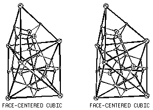
Figure 3.7. Critical Net Illustration of Face-Centered
Cubic.
 and
and  3m) and octahedral
(432 and m
 m) groups
can only accommodate peaks or pits, not passes nor pales, because of
their body-diagonal 3-fold axes. All of the other
32 - 5 = 27 possible point group
site symmetries in a space group can accommodate
any of the four critical points.
pits
 1
1
peaks  1
1
pales - pits  0
0
passes - peaks  0
0
passes - pales + pits  1
1
pales - passes + peaks  1
1
 ("triclinic simple-cubic" packing).
This count is identical to that for the four topology Betti numbers of
a 3-torus. Betti numbers are topological invariants used in the
derivation of the Morse inequalities.
 m
while hcp has ABAB... which requires
space group P63/mmc. Our
critical-net-on-orbifold convention defined in Sect. 4 incorporates
critical net, singular set, and lattice complex information to provide a full
global topology characterization, thus resolving
ambiguities such as the fcc versus hcp case.
 2.2. Euclidean 2-Orbifolds from Plane Groups
 Crystallographic
Topology Home Page